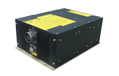
WS-1PH series inverter is a single-phase inverter designed by W&H-GAMAY. for civil and industrial electronic equipment. It is a kind of conversion device that can covert the direct current 12VDC, 24VDC, 48VDC into 60Hz/110V or 50Hz/60Hz/220V single-phase AC output.
Product introduction
Working Principle Diagram
Product Parameter
|
Model Items |
WS24-1PH1200 |
WS24-1PH1200 |
WS48-1PH1200 |
WS300-1PH1200 |
WS600-1PH1200 |
|||||||
|
Input |
Input voltage |
12VDC |
24VDC |
48VDC |
300VDC |
600VDC |
||||||
|
Voltage range |
DC9-18V |
DC18-36V |
DC36-72V |
DC200-400V |
DC500-700V |
|||||||
|
Current (Arms MAX) |
340 |
165 |
82 |
15 |
6 |
|||||||
|
Output |
Power(VA) |
1200 |
||||||||||
|
Voltage(Vac) |
110 |
220 |
110 |
220 |
110 |
220 |
110 |
220 |
110 |
220 |
||
|
Frequency(Hz) |
50/60 |
|||||||||||
|
Current (Arms) |
11 |
5.5 |
11 |
5.5 |
11 |
5.5 |
11 |
5.5 |
11 |
5.5 |
||
|
Efficiency(Typ) |
80% |
82% |
83% |
85% |
85% |
|||||||
|
Voltage Accuracy |
≤±2% |
|||||||||||
|
Total Harmonic Distortion |
≤3% |
|||||||||||
|
Load Regulation |
≤5% |
|||||||||||
|
Start-up time |
≤1S |
|||||||||||
|
Protection |
Over Load |
Exceed 120% of rated power, delay 30S; 150% delay 10S, and 200% delay 1S. |
||||||||||
|
Turn-off protection, restart after the load is normal. |
||||||||||||
|
Over Voltage |
>10%Turn-off output, restart to restore normal. |
|||||||||||
|
Over Heat |
Turn-off output, after temperature recovery, restart to restore normal. |
|||||||||||
|
Working Environment |
Working Temp.(℃) |
-40~50℃ |
||||||||||
|
Storage Temperature(℃) |
-55~85℃ |
|||||||||||
|
Operating Humidity |
10~90%RH,No condensation |
|||||||||||
|
Others
|
Test Voltage |
|
||||||||||
|
Insulation Resistance |
|
|||||||||||
|
Overall Dimension(mm) |
(L)330×(W)230×(H)130 (㎜) (electrical connector is not included.) |
|||||||||||
|
Weight(Kg) |
≤8.5Kg |
|||||||||||
|
Note: 1.Harmonic measurement: Use the 0.1mm2 twisted pair wire, after two turns of winding on the Φ10 ferrite core in terminal and parallel connected with a 0.1uF capacitor, and measure under the condition of 20MHz oscilloscope bandwidth. 2.Voltage Accuracy: including setting error and load regulation;The power level, output voltage and output frequency in the table are standards, it also can be customized if there's special requirements.
|
|
|||||||||||


2) Connection Definition
|
Input/Output Electric Connector |
XS1→(Plug Type: JY3102E24-11P) |
|||
|
|
Pin No. |
Connection Definition |
Pin No. |
Connection Definition |
|
A |
110VAC or 220VAC Output L |
E |
Earthing |
|
|
B |
Null |
F |
28VDC-input |
|
|
C |
110VAC or220VAC Output N |
G |
Null |
|
|
D |
28VDC+Input |
H--I |
remote control switch |
|
|
Phase-locked connector |
XS2→(Plug Type:XK24J12G ) (For single phase output is not need.) |
|||
|
|
Pin No. |
Connection Definition |
Pin No. |
Connection Definition |
|
1 |
|
7 |
|
|
|
2 |
|
8 |
|
|
|
3 |
|
9 |
|
|
|
4 |
|
10 |
|
|
|
5 |
|
11 |
|
|
|
6 |
|
12 |
|
|
|
Note: 1. The phase-locked socket needs to be connected only when it is combined into a three-phase power supply, and the single-phase output phase-locked socket does not need to be connected. 2. When remote control switch wiring, the allowable current of the conductor must not be less than 5A. |
||||
Online booking