Service hotline:86-029-89186965
 ENGLISH
  CHINESEService hotline:86-029-89186965 ENGLISH CHINESE
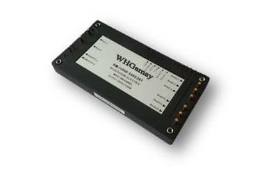
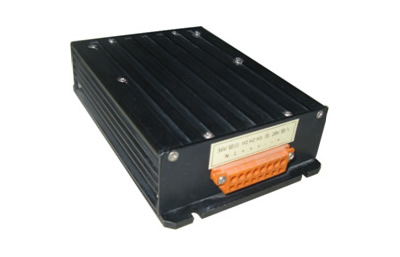
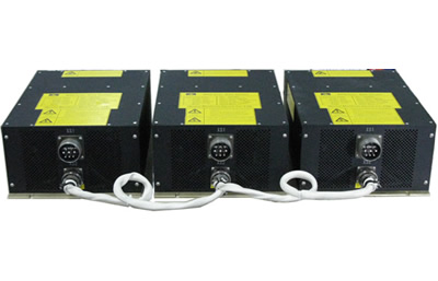
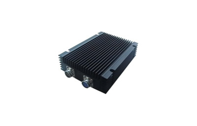
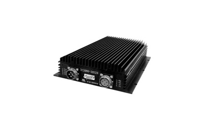
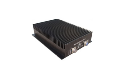
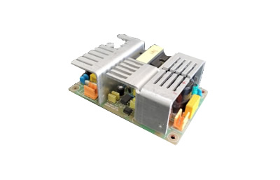
WD1000P series DC-DC Power Module is a new generation product developed by W&H-GAMAY. It has high voltage and wide range power input (200-400Vdc), and adjustable output (22-30.8Vdc), the output power is 1000W; Standard all brick package, closed structure.
Product introduction
Product Parameter
|
Name |
Parameter |
Remark |
|
|
Product Model |
WD1000P-540S28T |
WD1000P-300S28T |
|
|
Rated input voltage(Vdc) |
500 |
300 |
|
|
Input Voltage Range (Vdc) |
380-650 |
200-400 |
|
|
Output Voltage (Vdc) |
28 |
|
|
|
Output Adjustable Range |
-20%~+10% |
|
|
|
Maximum Output Current(A) |
35.7 |
|
|
|
Typical Value of Ripple and Noise(mV) |
100 |
|
|
|
Efficiency (%) |
93.5 |
|
|
|
Overall Dimension |
116.8*61*13.9mm(L*W*H) |
|
|
|
Note:1, Unless otherwise stated, all specifications are measured at the operating temperature of 25℃, rated input, full load output conditions; 2, Above products can provide M file, for other output voltage, please contact us. |
|||
1. Input Characteristics
|
Items |
Minimum |
Typical Value |
Maximum |
Unit
|
Remark |
|
|
Model |
WD1000P-500S28T |
|||||
|
Input |
Voltage Range |
380 |
500 |
650 |
Vdc |
|
|
Under Voltage Protection Point |
345 |
355 |
365 |
Vdc |
Output with half load |
|
|
Under Voltage Recovery Point |
355 |
365 |
375 |
Vdc |
Output with half load |
|
|
Over voltage Protection Point |
675 |
685 |
700 |
Vdc |
Output with half load |
|
|
Over voltage Recovery Point |
650 |
665 |
680 |
Vdc |
Output with half load |
|
|
Model |
WD1000P-300S28T |
|||||
|
Input |
Voltage Range |
200 |
300 |
400 |
|
|
|
Under Voltage Protection Point |
180 |
185 |
190 |
|
|
|
|
Under Voltage Recovery Point |
190 |
195 |
200 |
|
|
|
|
Over voltage Protection Point |
410 |
420 |
430 |
|
|
|
|
Over voltage Recovery Point |
400 |
405 |
410 |
|
|
|
|
ON/OFF Remote control (Negative Logic) |
2.4 |
|
18.0 |
Vdc |
High level, without output |
|
|
-1 |
|
0.8 |
Vdc |
Dangling or low level, normal output |
||
|
Maximum Input Current |
|
|
5.5 |
A |
Vin=380Vdc,Po=1000W |
|
|
No-load Input Current |
|
40 |
60 |
mA |
Rated input, no load output Tc=25℃ |
|
|
Input Great Instantaneous Current |
|
|
5 |
A2s |
Vin=500Vdc, External high frequency low ESR 470µF; 22uF electrolytic capacitor , inductance 12uH |
|
|
Input External Capacitor |
22 |
47 |
100 |
µF |
High frequency low ESR aluminum electrolytic capacitor, withstand voltage≥800 Vdc; When the operating temperature is lower than -25 ℃, add a 2.2μF/1000Vdc CBB capacitor. |
|
2. Output Characteristics
|
Items |
Minimum |
Typical Value |
Maximum |
Unit |
Remark |
|
|
Output Voltage Set Value |
27.72 |
28.00 |
28.28 |
Vdc |
Rated input, output with half load |
|
|
Output Voltage Regulated Accuracy |
|
|
±1 |
% |
Input full range,output no-load to full load |
|
|
Voltage Regulation |
|
|
±0.2 |
% |
Input full range,rated output current |
|
|
Load Regulation |
|
|
±0.5 |
% |
Rated input, output full range |
|
|
Output Adjustable Range |
-10 |
|
+10 |
%Vo |
Output power≤Maximum output power output current ≤Maximum current output |
|
|
Current-sharing Bus Voltage |
4.75 |
5.00 |
5.25 |
Vdc |
Rated input, output full load |
|
|
Sharing Current |
|
±5 |
±10 |
% |
Vout=28Vdc,Io=17.85-35.7A |
|
|
Output Over-current Protection |
40.0 |
42.0 |
44.0 |
A |
Vin=500Vdc,Vout=28Vdc; Constant current firstly, then hiccups, and self-recovery |
|
|
Output Over-voltage Protection |
33 |
35 |
37 |
Vdc |
Vin=500Vdc,Io=35.7A;Locking mode |
|
|
Auxiliary Power Output Voltage |
9 |
11 |
13 |
Vdc |
Output 0-20mA |
|
|
Auxiliary Power Output Current |
|
|
20 |
mA |
|
|
|
Ripple + Noise (peak-to-peak ) |
|
200 |
350 |
mV |
Test method is shown in Figure (16) |
|
|
Output External Capacitor |
1000 |
1500 |
|
μF |
Solid capacitor or polymer capacitor |
|
|
Output Capacitive Load |
|
|
3000 |
μF |
Pure resistance mode |
|
|
Output Voltage Rise Time |
|
20 |
40 |
ms |
Output voltage from 10% rise to 90%(Rated output capacitance) |
|
|
Remote Boot Output Voltage Rise Time |
|
20 |
40 |
ms |
The input is powered on first, then turn ON/OFF, the output voltage from 10% rise to 90%(Rated output capacitance). |
|
|
Turn on Delay |
|
|
1500 |
ms |
The input voltage rises to the undervoltage restore Point until the output voltage rises to 10%. |
|
|
Remote Startup Delay |
|
600 |
1000 |
ms |
Input Power-on first, and then turn ON/OF until the output voltage rises to 10%. |
|
|
Dynamic Response to Overshoot Amplitude |
|
840 |
1400 |
mV |
25%-50%-25%,50%-75%-50% load step change,di/dt= 2.5A/µs, output external 1000μF solid-state capacitor or high-molecular polymer capacitor. |
|
|
Dynamic Response Recovery Time |
|
500 |
1000 |
uS |
||
|
On off Output Voltage Overshoot Amplitude |
|
|
5 |
%Vout |
|
|
|
Efficiency |
100% Load |
91.5 |
93.5 |
|
% |
Vin=500Vdc,Vo=28Vdc,Tc=25℃ |
|
50% load |
91.5 |
93.5 |
|
% |
||
3. General Characteristics
|
Items |
Minimum |
Typical Value |
Maximum |
Unit |
Remark |
|
|
Isolation Voltage
|
input-output |
4250 |
|
|
Vdc |
Testing Condition:10mA/60s; No breakdown. |
|
Input to Case |
3535 |
|
|
Vdc |
||
|
Output to Case |
1500 |
|
|
Vdc |
||
|
Insulation Resistance |
100 |
|
|
MΩ |
Relative humidity:90%; Under standard atmospheric pressure, 500Vdc voltage. |
|
|
MTBF |
2 |
|
|
MHrs |
Rated input, rated output,Tc=25℃ |
|
|
Operation Temperature |
-55 |
|
80 |
℃ |
M grade, aluminum substrate temperature |
|
|
-40 |
|
80 |
℃ |
T grade, aluminum substrate temperature |
||
|
Storage Temperature |
-55 |
|
125 |
℃ |
Working Temperature |
|
|
Relative Humidity |
5 |
|
95 |
% |
non-condensing |
|
|
Storage Humidity |
5 |
|
95 |
% |
non-condensing |
|
|
Size |
116.8*61*13.9 |
mm |
L * W * H |
|||
|
Weight |
225 |
g |
|
|||
Structure & Size
1. Overall Dimensions (Unit:mm)

|
Pin |
Name |
Function |
|
1 |
NC |
NOT CONNECTED |
|
2 |
NC |
NOT CONNECTED |
|
3 |
ON/OFF(+) |
ON/OFF Remote control input positive end |
|
4 |
ON/OFF(-) |
ON/OFF Remote control input negative end |
|
5 |
Vin(+) |
Input voltage positive end |
|
6 |
Vin(-) |
Input voltage negative end |
|
7 |
Vaux |
Auxiliary power output positive end((reference: Vout(-)) |
|
8 |
Start_Sync |
Synchronize start(optional) |
|
9 |
Ishare |
Current sharing end |
|
10 |
Trim |
Output voltage trimmer end |
|
11 |
S(+) |
Remote compensation positive input end |
|
12 |
S(-) |
Remote compensation negative input end |
|
13、14、15 |
Vout(-) |
Output voltage negative end |
|
16、17、18 |
Vout(+) |
Output voltage positive end |

Components recommendations
|
Components Tag Number |
Description |
|
R1,R2 |
470KΩ,1/2W |
|
C1,C2 |
47μF/450Vd Capacitor |
|
C3 |
solid-state capacitor or high-molecular polymer capacitor,1500μF/50V |
Remote Control Switch
The control mode of the remote terminal is: negative logic.|
Control Method |
electrical level of ON/OFF |
||
|
low level |
dangling |
high level |
|
|
negative logic |
Module turn on |
Module turn on |
Module turn off |

Figure (14) Remote control mode diagram

Figure (17) Output voltage up-regulation diagram Figure(18) Output voltage down-regulation diagram
Up-regulation resistance formula Down-regulation resistance formula

Note:
1. 
2. Vout: Output voltage after output adjustment
3. Vout norm: Output nominal voltage: 28Vdc
4. The maximum rated power of the module remains unchanged, if the output voltage increases, the output current will decrease accordingly.
5. The maximum output current of the module is unchanged, if the output voltage is reduced, the maximum output current remains unchanged.
6. The maximum output voltage cannot exceed 30.8Vdc;The input voltage less than 450Vdc,It can only be raised by 5%.
7. The ends of S(+) and S(-)cannot be used suspended.If the ends of S(+) and S(-) are not used, the end of S(+) can be connected to Vout(+),and the end of S(-) can be connected to Vout(-).
8. When adjusting the output voltage during the operating state, adjust the corresponding resistance value slowly; If need to quickly adjust the resistance value of the resistor, be sure to turn off the machine.
Output Voltage Remote Compensation

Figure (19) Output Voltage Remote Compensation Circuit
Note:
1. The maximum output voltage cannot exceed 30.8Vdc;The input voltage less than 450Vdc,It can only be raised by 5%.
2. The maximum rated power of the module remains unchanged, if the output voltage increases, the output current will decrease accordingly.
3. The polarity of the output voltage of S(+) and S(-) must be consistent; Otherwise, the power module will enter protection state.
Online booking